Inspect each thread
to understandthe whole joint.

Detailed thread modeling · Structured meshing · Joint simulation

From thread profile and fit to contact, preload and local response.
Investigate how small geometry changes affect the design.

For the design and analysis of threaded joints.

Precise geometry · M30 × 3.5drag rotate
TD Forge Actual Software's M30 Precise Threaded Bolt
thread details
start point of connection
The same geometry, different observation scales.Starting with the thread profile
THREAD DESIGNER® ENGINEERING SUITE 4.0
Thread Profile and FitGeometry and meshAnalysis and evidence
downward exploration

Use a thread profile
to define amating pair.

Define profiles and combined thread configurations explicitly. Design the internal and external profiles together and check clearance and constraints before developing a new thread concept.

M30 × 3.5Internal and external contours / axial cross-section
131415r / mmP = 3.5 mmaxial position / mm
external threadinternal threadFit Gap
Metric

Start with a standard profile and adapt it to your design.

Start with a metric profile and examine internal and external thread dimensions, tolerances and fit. Keep design parameters and geometric constraints in the same project.

tightloose

Thread angle 60° · Pitch 3.5 mm

Go from standard fits to custom profiles, combined threads and special fasteners.

The interactive profiles illustrate fit geometry. The clearance slider is a visual aid only.

Bring geometry, mesh and loads
together in onejoint model.

Model the bolt, nut and clamped members together. Keep the engineering context from part definition and assembly through meshing and analysis setup.

Precise thread / PARTM30 × 3.5
Real M30 CAD Workbench

Actual case geometry, with the thread root, flank and axial segments represented as inspectable features.

Decide
which details to model.

Choose an equivalent or detailed representation. Define the root radius, threaded length, plain shank and support geometry to suit the analysis.

  • III / IV Level expression
  • Parametric fastener
  • Internal and external cooperation design

Assemble the parts
and retain the design intent.

Align, face-align, offset, and phase with the nut to allow inspection, adjustment, and further editing of the assembly position. Sectioning and disassembly help to see the internal structure.

  • location relationship
  • CAD import
  • Sectioning and disassembly

Refine the mesh
where local detail matters.

Precise threads are connected to structured hexahedral meshes. Thread root details, region transitions, and quality checks organize the discrete, allowing the mesh to carry engineering meaning.

  • structured HEX8
  • compatible mixed transition
  • Quality and Area Inspection

The joint's response
begins with preload.

Materials, friction contact, preload, boundary, and external load together compose the analysis. Observe the response along the analysis step, linking local stress with the overall connection state.

  • Static and nonlinear
  • CalculiX solver
  • Abaqus interoperability

Compare what changes
when you change thethread profile.

M30 × 3.5, four-part connection. Maintain consistency in material, load, contact, and mesh strategy, and compare M and MJ thread profiles. Let changes correspond to causes, and let conclusions return to conditions.

See where the joint responds.

Section the structure, observe how stress passes through each thread
From equivalent stress to plastic strain, let local hotspots be traceable.

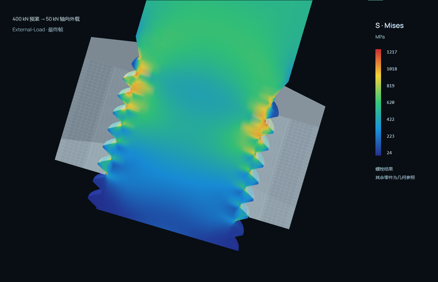
M30 × 3.5 Metric · 10.9 class bolt
M30 bolt external load step real equivalent stress cross-section cloud map, with high response areas appearing at the thread root region.
400 kN preload → 50 kN axial external loadExternal-Load · Final frame

The case's real field data has been saved · Web results view

Inspect the response along the engaged thread roots.

Stress concentration factor Kt
0.01.32.63.95.2123456mesh sequence numberM · 1st thread · 4.555M · 2nd thread · 2.984M · 3rd thread · 1.781M · 4th thread · 1.368M · 5th thread · 1.173M · 6th thread · 0.925MJ · 1st tooth · 4.230MJ · 2nd tooth · 2.801MJ · 3rd tooth · 1.691MJ · 4th tooth · 1.302MJ · 5th tooth · 1.120MJ · 6th tooth · 0.895
M · Metric Thread ProfileMJ · arc thread root

Case original results · two sets of matching internal and external thread profiles · comparison under the same operating condition

View operating conditions, metrics, and applicability

The linear-elastic case uses peak integration-point S33 at the roots of six fully engaged external threads. Normalize using the bolt force computed for that step and the actual root section area of each profile. Step two applies an external axial load after FIX_LENGTH. Local elastic peaks alone do not establish strength compliance.

In the elastoplastic case, the bolt uses a representative property class 10.9 material curve. The nut and plates remain elastic. Stress amplification after yielding is outside the definition of linear-elastic Kt. For plasticity comparisons, use thread-root p99 PEEQ and the extent of the plastic zone. Peak plastic strain remains sensitive to mesh size.

Web reads saved Abaqus case data, without real-time solving. Specific results only correspond to the conditions of this case.

Keep details in context
and work in ato analysis.

Organize parts, assembly, mesh, and analysis within the same engineering. Leave the view to the structure, and let parameters, tasks, and results be expanded when needed.

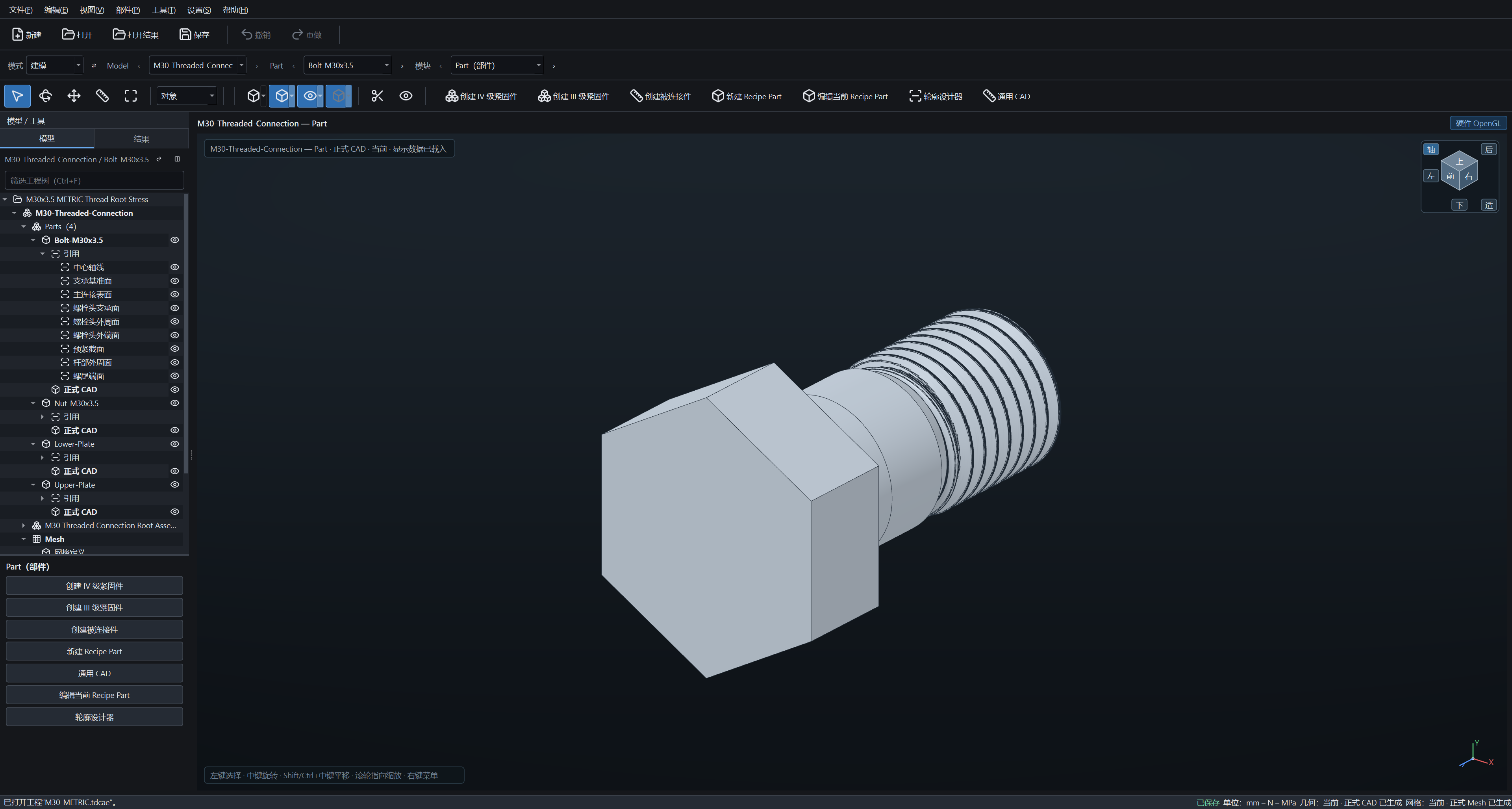
M30 precise thread, parameterized parts and engineering tree.Actual desktop interface · Example engineering

Modeling and simulation share the same engineering setup.

PartAssemblyMeshAnalysisResults

Turn design intent
intoengineering actions.

Consult, review, operate. AI is connected to objects, parameters, and tasks in current engineering, helping you move from 'what to study' to 'how to proceed next.'

Understand the engineering context

Organize around the selected part, mesh, analysis, and results for questions and answers, reducing repeated descriptions

Preview changes first

Before operation, clearly see the impact, proceed within the confirmed task range, and retain verifiable operation records.

Build a repeatable research workflow

From scheme preparation, task execution to result comparison, let repetitive work form a continuous process.

AI is an optional collaborative capability, and the model service is connected according to user configuration.

engineering collaboration demonstration
research task

Compare the M and MJ profiles of an M30 thread. Use the same load case, check the mesh, and then compare thread-root response.

From a goal, expand verifiable engineering steps.

  1. Reading Engineering and Conditions

    Confirm the thread profiles, materials, and load baseline of the two groups.

    preparation
  2. Preview this operation

    Establish comparison task, retain original plan.

    to be started
  3. Verify mesh with results

    Check case records and read the corresponding analysis step.

    to be started
  4. Organize Comparison Basis

    Associate thread root response, convergence, and interpretation conditions.

    to be started

Pre-set interactive demonstration; no model connection service, no solver execution.

Use a single analysis
to explore a widerdesign space.

From a model's response, to a group of solution understanding. TD Forge's product direction is to connect geometric design, analysis preparation, and engineering judgment continuously.

exploration

Connect parameter changes to design decisions.

Around thread profile, thread root, engagement length, and preload scheme, conduct parameter studies, sensitivity analysis, and optimization. Retain the baseline, compare the benefits, and also the costs.

advancement

Turn repeated work into a workflow you can resume.

More rich modeling and mixed mesh, more automatic convergence study, loading organization, and task scheduling, leaving energy for truly needed judgment issues.

joint

Review local response alongside the rest of the evidence.

Extend to per-tooth load, contact, and plastic study, professional post-processing, and verifiable reports. Gradually connect design verification, knowledge data, and test results.

Relate local details to the full operating conditions.

Forge focuses on a single thread, a segment of engagement area's geometry and response. Kit collaboration starts with verifying the same joint's dimensions, loads, and verification conditions.

Dimensions and design basis
TD Atlas Supports thread size and modeling knowledgeTD Axiom Establish standard verification and design benchmarks to clarify input context for detailed studies.
Local and overall analysis
TD Nexus For complex structures and connection groups, Forge is for fine threads. The results at two scales need to be compared under consistent loading conditions and boundary conditions to discuss the relationship between local response and overall force transmission.
Testing and Operating Conditions
TD Sense Organize independent tests and analyses. Collaboration planning is in progress,TD Cadence record of the assembly processTD Sentinel The service observation can provide conditions for subsequent analysis.

Cross-product data collaboration belongs to the kit planning direction, specific integration is subject to official release notes.

Study the thread detail
that matters to your next design.

Communicate with the product team about structural, thread profile design, or connection analysis requirements.

Discuss your joint analysis requirements
TD Forge · Actual software interface
TD Forge Actual Software Interface Original